|

 Principle of Operation Principle of Operation
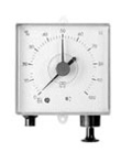
The Pneumatic Tank Contents Gauge measures the hydrostatic liquid head pressure at the bottom of the tank which, depending on the specific gravity of the liquid and the liquid head, is variable. Normally such liquid head measurement starts approximately 20 mm above the bottom of the tank and the liquid head pressure is converted into the required units on the instrument dial. The basic dial displays the liquid height in %. Should display of the contents be required in litres a slide in scale can subsequently be added. Pressure is built up in the capillary tube by means of the pump incorporated in the gauge, until equivalent to the hydrostatic pressure above the bottom of the tank. The pointer has now reached the maximum reading, and the pressure created by the pump has displaced the liquid column from the standpipe. The air escapes from the standpipe end at the bottom of the tank in bubbles, whilst the pointer remains in position to be read off.
Instrument Description
Universal, Pneumatic Tank Contents Gauge with performance membrane. Housing suitable for wallmounting and manufactured from high-impact plastic. Fully adjustable for tank heights between 900 and 3000 mm for measurement of light fuel oil (specific gravity = 0.84).
Remote indication up to 50 m. Linear performance membrane. Zero-correction.
Accurate to within +/- 3% of full scale deflection.
Semipermanent indication, i.e. pump seals off capillary system in upper dead centre, pointer remains temporarily in position and then falls again very slowly. The "oil stoppage air cushion" thereby created protects the performance membrane. Pointer for consumption control. Universal capillary connection suitable for hose or copper tubing with 6 mm outside diameter or Pneumofix kit. Indication on basic scale in % liquid height irrespective of tank shape. Slide-in scales calibrated in litres also available for oval, cubic and cylindrical tanks of all DIN ranges.
Application
Standard measuring range for liquid heights from 900 to 3000 mm light fuel oil (if the unit is intended for use with other liquids, please ask for index table for adjustment).
Remote indication up to 50 m.
Gauge suitable for wall mounting.
Temperature range: -5°C to +55°C. Gauge must be suitable protected from rain, snow etc.
Operation
Pull out pump briskly to stop and release. In the case of long capillary tubing this action should be repeated until the reading is constant, at which point the reading may be taken. If the capillary tubing is tight the pointer will remain in the read-off position for a long time. In order to achieve precise reading it is nevertheless recommended that the pumping action be repeated prior to each reading.
Installation Instructions
1. Gauge Mounting
Fix the unit in place with two half round wood screws, 5 mm shaft and 10 mm head diameter.
2. Capillary Installation
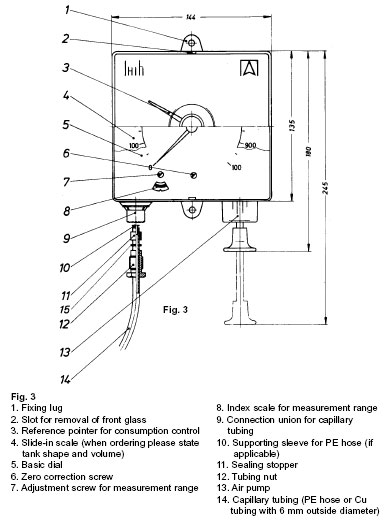
Assemble capillary tubing in tank. Use either copper tubing or oil-resistant Buna N tube with weight. Capillary tubing 20 mm from tank bottom. It is recommended that the Pneumofix (see fig. 2) kit be used. If not threaded connection is available on the tank, several capillaries can be united with a 1" threaded connection using the combination adaptor Euroflex 3 (see fig. 1). Install capillary tubing with fall towards the tank avoiding kinks and sharp bends (no water traps!). Install condensate trap where instrument is mounted below level of liquid and where there is a possibility of condensate forming within the capillary tubing. When connecting capillary tubing to gauge, slide adaptor parts onto tubing or hose in sequence as illustrated in fig. 3, pass hose or tubing into connection union as far as stop and tighten tubing nut gently. For PE hose use ferrule as supporting sleeve.
3. Instrument adjustment
(see fig. 3) Remove front glass. Adjust measurement range (which for measurement of light fuel oil is identical with tank height) on index scale precisely using index adjustment screw (to ensure correct reading!). Set pointer to 0 using zero correction screw. Rotate screw a maximum of one revolution to right or left until pointer is at 0. Once the tank has been filled and the pump operated the system must be rendered pressureless for the purpose of zero correction adjustment, which can be done by either detaching the capillary tubing from the connection union, or by briefly opening the condensate trap. Where applicable, place litre scale in position and carefully snap cover glass back into place. Should litre scale be ordered afterwards, please state tank shape and volume.
Fault Finding
1. Pointer hardly moves off the zero mark when the pump is operated or drops off again very quickly: leaking capillary lines or connections - check for leaks!
2. Pointer goes beyond the 100% mark on the scale or pump does not return to its stop: capillary line or connection is blocked or twisted, or measurement range is incorrectly adjusted.
3. Incorrect reading: gauge has been incorrectly adjusted (check tank dimensions and/or correct tank height on index scale).


|


 Principle of Operation